In this article, you will learn how to set up the remote nodes for your Wifi Smart Thermostat, including the wiring of the sensor and the relay to the ESP32 board, and how to upload the sketch with the Arduino IDE.
- Introduction
- Download the sketches
- How to upload the sketch to the ESP32.
- Diagram for the relay node
- Diagram for the temperature/humidity node
- Diagram for the hybrid node.
Introduction
The first thing you have to do is to decide how many nodes your installation will have. You need at least one node, that means, one ESP32 MCU, with a relay and a temperature/humidity sensor, like the one in the picture:
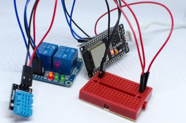
We call this node a “hybrid node” because it controls both things: the temperature sensor, and the relay.
You could use this node to replace the classical thermostat that you have on the wall in your living room. Normally those thermostats are connected with the boiler. You have to connect the wires that go to the boiler with the relay.
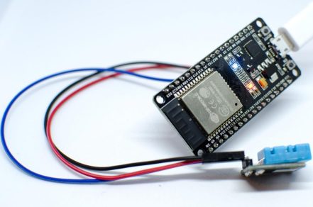
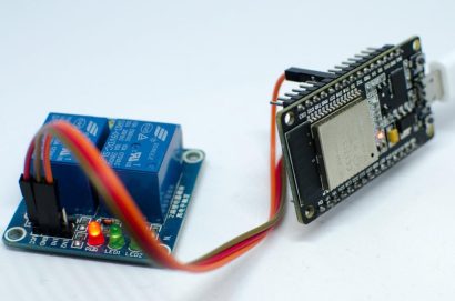
Another option is to split the node above, and have two ESP32 MCU’s, one for the relay, and one for the temperature sensor. You can leave the temperature node somewhere in your living room, and the relay node could be placed directly in the boiler. The following pictures are examples of this configuration:
And of course, you can add as many temperature/humidity nodes as you want. But you can have only one relay per thermostat and boiler.
Depending on which nodes do you need, you will have to upload a specific sketch to the ESP32. Before uploading them to the sketch, don’t forget to configure your Wifi SSID and password, and the name for the node.
Download the sketches for the ESP32
There are three sketches, depending on which type of node you are planning to assembly. You can download a zip file with all the available sketches from our resources page.
Upload the sketch to the ESP32
The next step is to upload the appropriate sketch to the ESP32. You have to decide if the ESP32 will be a temperature node, a relay node or a hybrid node, and upload the corresponding sketch using the Arduino IDE.
We recommend to upload the sketch to the ESP32 before connecting the relay/temperature sensor. We detected problems when uploading the sketch to some ESP32 mcu’s where all the hardware was already wired, an the problems where gone when disconnecting all the peripherals.
- Download, install and open the Arduino IDE. You can download it from here.
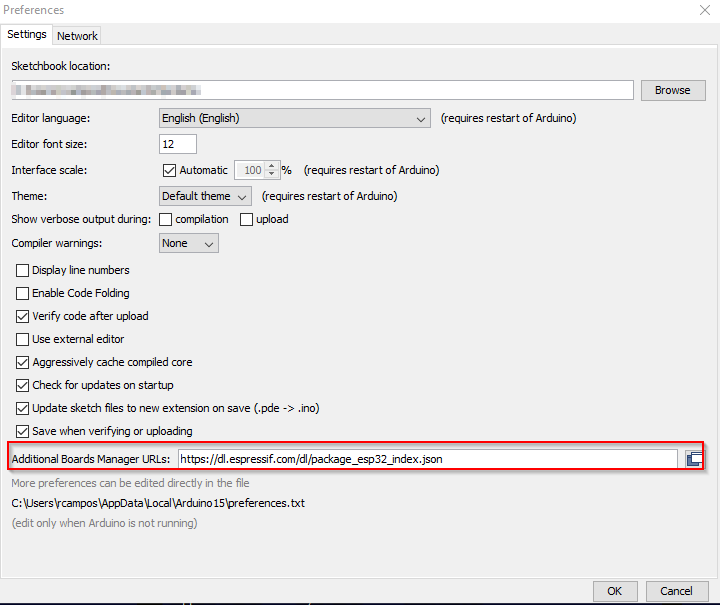
- Start the Arduino IDE, and configure the espressif ESP32 repository: open the File menu -> Preferences.
- Enter the URL https://dl.espressif.com/dl/package_esp32_index.json into the Additional Board Manager URLs field, like in the example below:
- Open the Tools Menu -> Board -> Boards Manager and install the esp32 platform (search for esp32).
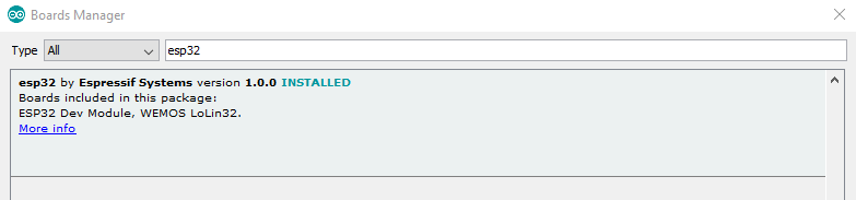
- Select your board from the Tools -> Board menu. For example, select the ESP32 Dev Module from the boards menu.
- Now, install the DHTesp library, if it is not already installed. Open the Library Manager under Tools -> Library Manager and search for “dhtesp”. Install the library “DHT Sensor Library for ESPx by beege_tokio”.
- Open the sketch you want to upload to the board, and customize the configuration section:
Look for a section in the sketch like the following. You have to write the name of your WIFI and the password used to connect to it. And if you are uploading the sketch for a temperature node, you have to uncomment the line corresponding to the temperature sensor you are using, like in the following sample:
/****** Start configuration section ******/


const char* ssid     = "YourWifiNameHere"; //Replace with your network SSID
const char* password = "YourPasswordHere"; //Replace with your network password
const String nodeName = "ReplaceThisName"; //Replace with the name for this node (example "Beed Room")


//Uncomment the appropriate type for your DHT Sensor.
DHTesp::DHT_MODEL_t DHT_TYPE = DHTesp::DHT22;
//DHTesp::DHT_MODEL_t DHT_TYPE=DHTesp::DHT11;

/****** End configuration section ******/- Connect the ESP32 board with an USB cable to your computer.
If having problems uploading the sketch to the ESP32, make sure that the cable you are using is in good condition, and is connected to a port in your computer that provides enough electrical supply. We have realized that using usb hubs, and cheap cables, does not work well. Connect the esp32 with a good usb cable to a good port in your computer.
- Make sure that you have selected the right COM port under Tools->COM. You can double-check what port the ESP32 is using by disconnecting the MCU, looking in this menu, and connecting it again, and checking which port appears.
- Open a Serial Monitor under Tools->Serial Monitor, and select 115200 baud as speed.
- Press the icon in the Arduino IDE to compile and upload the sketch to the board. This operation should take a little. You should see an output similar to the following:
Sketch uses 619398 bytes (47%) of program storage space. Maximum is 1310720 bytes.
Global variables use 41656 bytes (12%) of dynamic memory, leaving 286024 bytes for local variables. Maximum is 327680 bytes.
esptool.py v2.3.1
Connecting........_
Chip is ESP32D0WDQ6 (revision 1)
Features: WiFi, BT, Dual Core
Uploading stub...
Running stub...
Stub running...
Changing baud rate to 921600
Changed.
Configuring flash size...
Auto-detected Flash size: 4MB
Compressed 8192 bytes to 47...

Writing at 0x0000e000... (100 %)
Wrote 8192 bytes (47 compressed) at 0x0000e000 in 0.0 seconds (effective 5461.3 kbit/s)...
Hash of data verified.
Compressed 15072 bytes to 9733...

Writing at 0x00001000... (100 %)
Wrote 15072 bytes (9733 compressed) at 0x00001000 in 0.1 seconds (effective 996.5 kbit/s)...
Hash of data verified.
Compressed 619536 bytes to 374325...

Writing at 0x00010000... (4 %)
Writing at 0x00014000... (8 %)
Writing at 0x00018000... (13 %)
Writing at 0x0001c000... (17 %)
Writing at 0x00020000... (21 %)
Writing at 0x00024000... (26 %)
Writing at 0x00028000... (30 %)
Writing at 0x0002c000... (34 %)
Writing at 0x00030000... (39 %)
Writing at 0x00034000... (43 %)
Writing at 0x00038000... (47 %)
Writing at 0x0003c000... (52 %)
Writing at 0x00040000... (56 %)
Writing at 0x00044000... (60 %)
Writing at 0x00048000... (65 %)
Writing at 0x0004c000... (69 %)
Writing at 0x00050000... (73 %)
Writing at 0x00054000... (78 %)
Writing at 0x00058000... (82 %)
Writing at 0x0005c000... (86 %)
Writing at 0x00060000... (91 %)
Writing at 0x00064000... (95 %)
Writing at 0x00068000... (100 %)
Wrote 619536 bytes (374325 compressed) at 0x00010000 in 5.8 seconds (effective 859.0 kbit/s)...
Hash of data verified.
Compressed 3072 bytes to 144...

Writing at 0x00008000... (100 %)
Wrote 3072 bytes (144 compressed) at 0x00008000 in 0.0 seconds (effective 2048.0 kbit/s)...
Hash of data verified.

Leaving...
Hard resetting via RTS pin...
The ESP32 will be restarted, and after a while, you should see something similar to the following in the serial monitor
Connecting to YourWifiName
 ..
 WiFi connected
 IP address: 192.168.2.160
 MAC: 30:AE:A4:39:44:FC
 Signal strength (RSSI):-32 dBm
As you see, the IP address of the node is listed in the boot message.
Now it is time to connect the temperature sensor and/or relay to the ESP32. Disconnect the USB cable, connect the needed peripherals, and connect the USB cable again. If the steps before have succeeded, the node is ready to use. You can check if the node works correctly invoking the IP address of the node in a browser. For example:
Invoque in your web browser the URL http://192.168.2.160, and you should receive something similar to the following:
{
     "type": "TH&Relay",
     "name": "Master node",
     "version": "3",
     "relay_error": "",
     "th_error": "",
     "mac": "30:AE:A4:39:44:FC",
     "relay_high": "0",
     "celsius": "18.30",
     "fahrenheit": "64.94",
     "humidity": "43.10",
     "wifi_ssi": "-33"
 }
Check the sections below, to learn how to connect the relay/temperature sensor to the ESP32.
How to set up the relay node
For the relay node, you will need an esp32 and a one channel relay. The relay may be a low level triggered relay, or a high level triggered relay. The sketch assumes that the relay is a high level triggered relay by default. If you want to use a low level triggered, please adjust the flag in the configuration section of the sketch:
//If you are using a HIGH LEVEL TRIGGERED Relay set the following flag to true
//If you are using a LOW LEVEL TRIGGERED Relay set the following flag to false
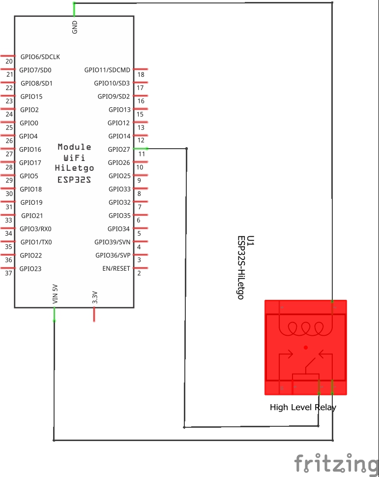
bool RELAY_IS_HIGH_LEVEL = true;The connections from the ESP32 to the relay are the following.
- GPIO27 pin of the ESP32 with the IN pin of the relay
- GND pin in the ESP32 to the GND Pin in the relay
- VIN (5V) pin in the ESP to the VCC pin in the relay
And of course, you have to connect the relay to the boiler. Please connect the relay to the boiler in a way that if the ESP32 is turned off, the boiler is turned off too. Normally you have to use the NO (normally open) connector of the relay.
And please, always stay safe when working with the relay and the boiler.
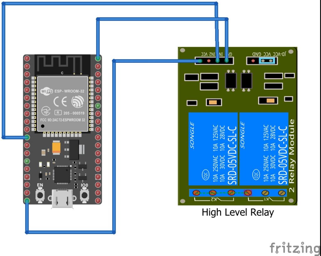
(open in a new window to enlarge)
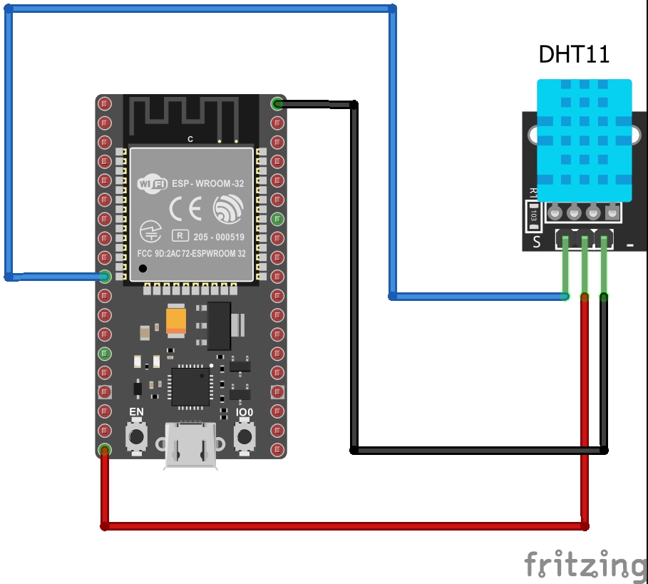
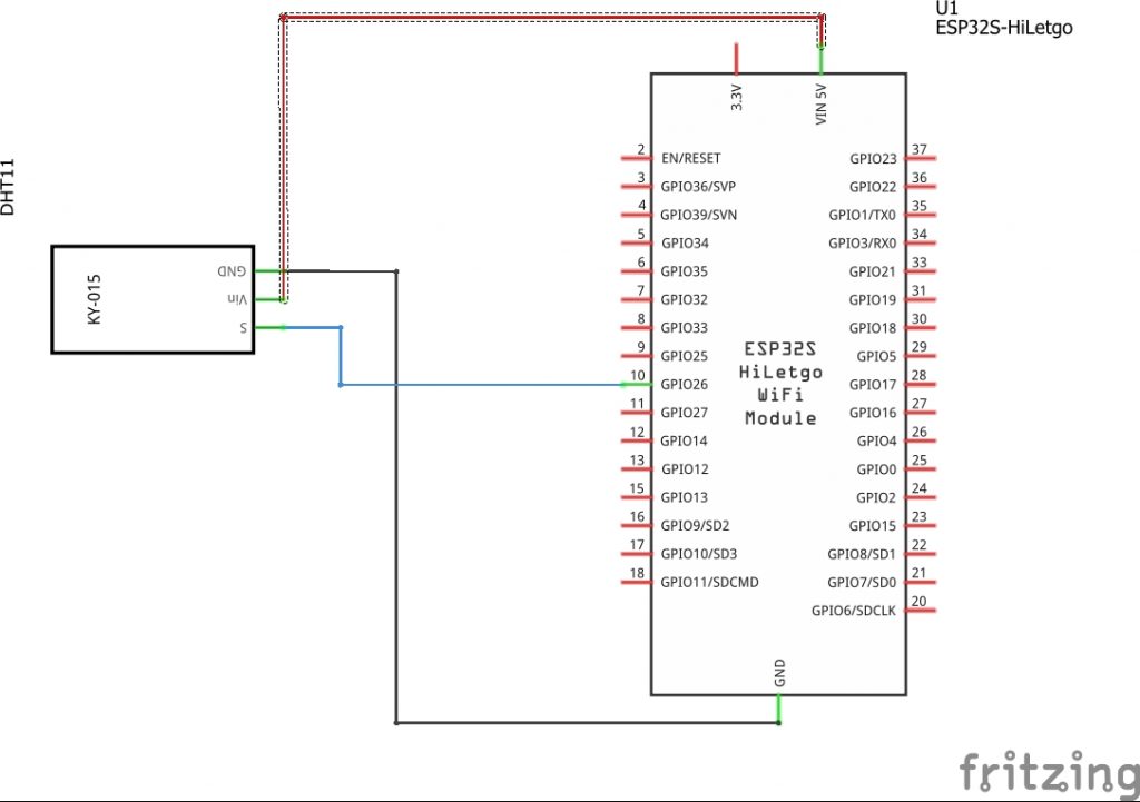
Setup of the temperature/humidity node
- GPIO26 pin in the ESP32 to the S pin in the DHT sensor
- GND pin in the ESP32 to the GND Pin in the sensor
- VIN (5V) pin in the ESP to the VCC pin in the sensor
(open in a new window to enlarge)
(open in new window to enlarge)
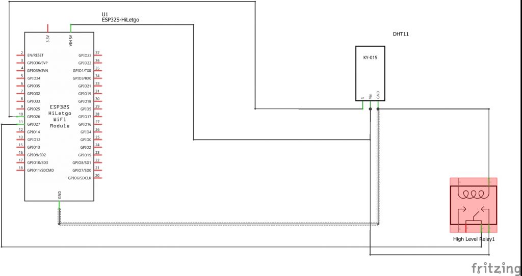
Setup for a hybrid node (relay & temperature sensor)
Regarding the relay, the steps are the same as for the “relay only” sketch (see above). Again, remember to take the appropriate precautions when manipulating the relay and your boiler.
- GPIO26 pin in the ESP32 to the S pin in the DHT sensor
- GPIO27 pin of the ESP32 with the IN pin of the relay
- You have to share the VIN and GND pins with the relay and the sensor. You can achieve this using a breadboard.
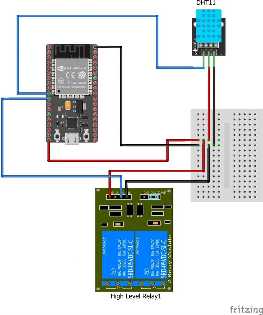
(open in a new window to enlarge)
(open in a new window to enlarge)
Don’t hesitate to visit our forum if you have questions or problems setting up your remote nodes.